Removing
1. Remove accessory drive belts, coolant pump pulley and alternator.
2. Remove the coolant pump plug and drain the coolant.
3. Remove the timing belt (see section "timing belt").
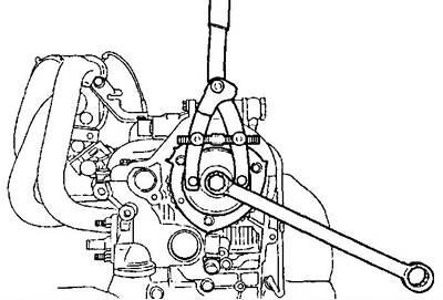
4. Fix the camshaft with a wrench from rotation and unscrew the bolt securing the camshaft pulley.
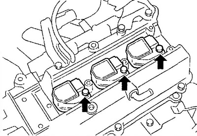
5. Remove ignition coils.
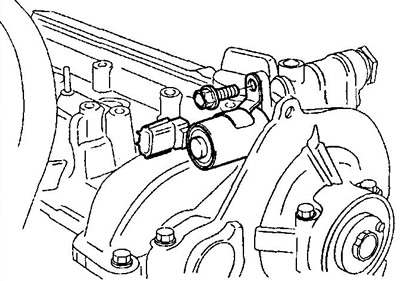
6. (EJ-VE) Remove the DVVT system valve.
7. Disconnect the vacuum hose from the intake manifold and cylinder head cover.
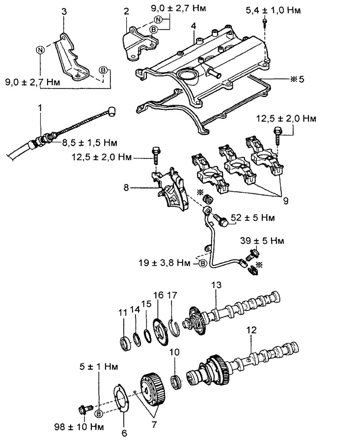
Removal and installation of a head of the block of cylinders (EJ-DE).
1 - accelerator cable,
2 - bracket No. 1,
3 - bracket No. 1,
4 - cylinder head cover,
5 - gasket,
6 - camshaft position sensor rotor,
7 - camshaft pulley,
8 - cover No. 1 of the camshaft bearing shells,
9 - cover No. 2 of the camshaft bearing shells,
10 - stuffing box,
11 - plug,
12 - camshaft No. 1,
13 - camshaft No. 2,
14 - retaining ring,
15 - wavy washer,
16 - auxiliary gear of the camshaft,
17 - spring ring.
8. Remove a rack from a cover of a head of the block of cylinders.
9. Turn away screws of fastening of a cover of a head of the block of cylinders and remove it from a head of the block of cylinders.
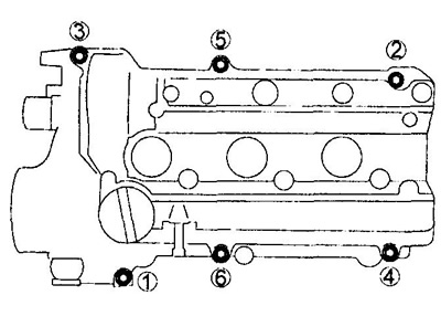
10. Remove camshafts No. 1 and No. 2.
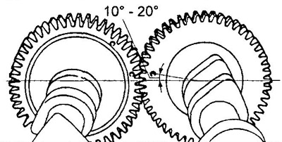
A) Rotate camshaft #2 (exhaust valves) behind the hex section as shown in the figure.
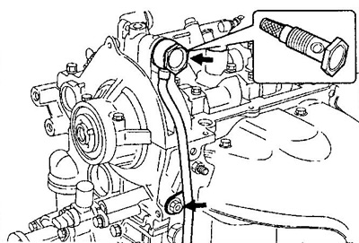
b) Loosen the oil pipe bypass fitting.
V) Turn out a bolt of fastening of an oil tube to a head of the block of cylinders.
G) Remove the bypass fitting of the oil pipe with the oil filter from the cover No. 1 of the camshaft bearing shells.
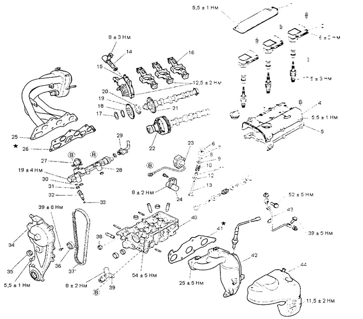
Removal and installation of a head of the block of cylinders (EJ-VE).
1 - ignition coil cover,
2 - ignition coil,
3 - spark plug,
4 - cylinder head cover,
5, 26, 41 - gasket,
6 - adjusting washer,
7 - pusher,
8 - crackers,
9 - spring plate,
10 - spring,
11 - oil scraper cap,
12 - spring seat,
13 - valve,
14 - valve of the DVVT system,
15 - cover No. 1 of the camshaft bearing shells,
16 - cover of the bearing shells of the camshafts,
17 - retaining ring,
18 - wavy washer,
19 - auxiliary gear of the camshaft,
20 - spring ring,
21 - camshaft No. 1,
22 - camshaft No. 2,
23 - ignition module,
24 - camshaft position sensor,
25 - intake manifold,
27 - fuel pressure pulsation damper,
28 - fuel manifold,
29 - fuel pipe No. 1,
30 - ring seal,
31 - nozzle insulator,
32 - nozzle,
33 - vibration isolator,
34 - timing chain cover,
35 - sealing sleeve,
36 - timing belt tensioner,
37 - timing belt,
38 - plug,
39 - crankshaft position sensor,
40 - cylinder head,
42 - exhaust manifold,
43 - oil pipeline,
44 - heat shield.
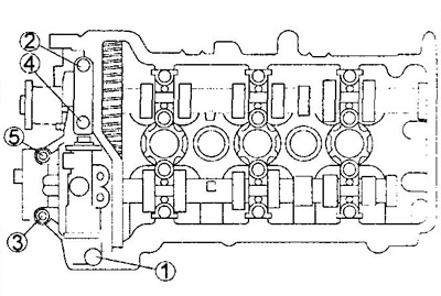
d) Remove cover No. 1 of the camshaft bearing shells by unscrewing the bolts in the sequence shown in the figure.
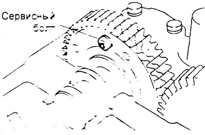
e) Install the service bolt, securing the auxiliary and drive gears.
- Service bolt - M5x0.8
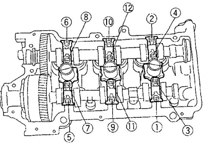
and) Turn away bolts of fastening of fastening of loose leaves of bearings of camshafts in the sequence shown in drawing.
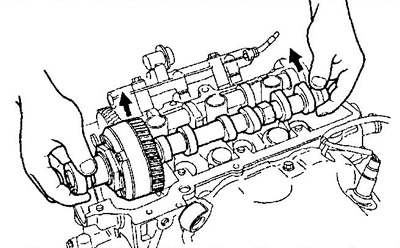
h) Remove the intake and exhaust camshafts.
Note: the camshafts must be lifted strictly horizontally, because. the slightest misalignment can damage the bearing shells.
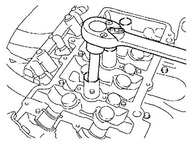
10. Turn out spark plugs.
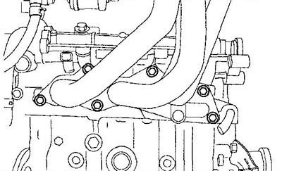
11. Remove the intake manifold with gasket.
Note: Do not reuse gasket.
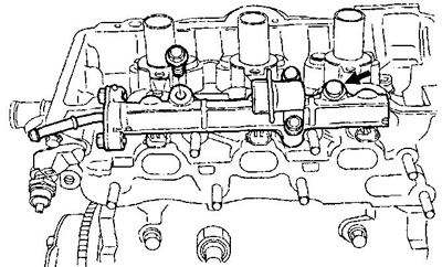
12. Remove the fuel manifold from the cylinder head.
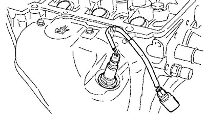
13. Remove the nozzles.
14. Disconnect the oxygen sensor connector.
15. Remove the exhaust manifold heat shield.
16. Remove the oxygen sensor.
17. Remove the exhaust manifold with gasket.
Note: Do not reuse gasket.
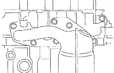
18. Remove the coolant inlet from the cylinder head.
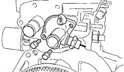
19. Remove the thermostat.
20. Remove the coolant temperature sensor,
21. Remove the crankshaft position sensor.
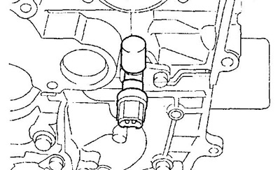
22. Remove the camshaft position sensor.
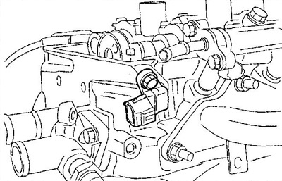
23. Turn away bolts of fastening of a head of the block of cylinders in the sequence shown in drawing, and remove a head of the block of cylinders.
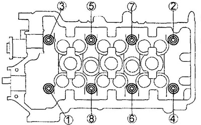
24. Remove the cylinder head gasket.
Note: Do not reuse gasket.
25. If necessary, disassemble the intake camshaft.
A) Fix the camshaft in a vise.
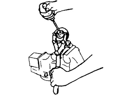
b) Lock the sub gear with the special tool and remove the service screw by turning the sub gear.
V) Remove the snap ring.
G) Remove the wave washer, auxiliary gear and circlip.
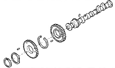
Note: (EJ-VE) do not disassemble the exhaust camshaft with DVVT sprocket.
Disassembly, inspection, cleaning and repair of the cylinder head
The procedures for disassembling, checking, cleaning, repairing and assembling cylinder head parts are described in chapter "Engine - General Repair Procedures".
Installation
1. Assemble the intake camshaft.
A) Install the circlip, sub gear and wave washer.
b) Install retaining ring.
V) Install the special tool in the two holes of the 6 mm sub gear.
G) Turn the sub gear clockwise, align the holes of the sub gear and driven gear, and install the service bolt.
2. Clean the surface of the cylinder block and install the cylinder head gasket.
3. Temporarily tighten the crankshaft pulley bolt.
4. Turn the crankshaft key up.
5. Install the cylinder head to the cylinder block.
6. Apply some engine oil to the threads and under the bolt heads. Install the bolts and tighten them in several passes in the sequence shown in the figure.
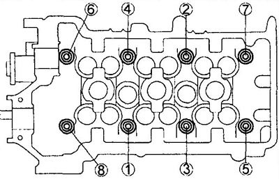
- Tightening torque - 54±5 Nm
Note: If any of the bolts are not tightened to the specified torque, replace them.
7. Install thermostat and coolant inlet.
8. Clean the threads of the new coolant temperature sensor, wrap the threads of the sensor with mounting tape and wrap it in the cylinder head.
- Tightening torque - 24±5 Nm
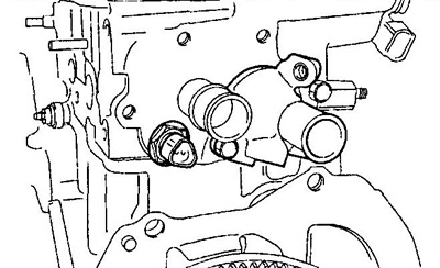
9. Clean the threads of the new coolant temperature sensor, wrap the threads of the sensor with mounting tape and screw it into the coolant inlet.
- Tightening torque - 24±5 Nm
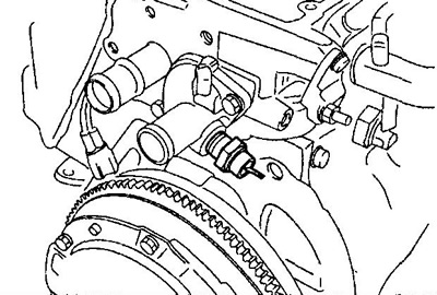
10. Install the crankshaft position sensor.
- Tightening torque - 8±1.6 Nm
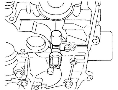
11. Install the camshaft position sensor to the cylinder head.
- Tightening torque - 8±1.6 Nm
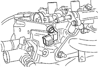
12. Install the exhaust manifold with a new gasket.
- Tightening torque - 25±5 Nm
13. Install the exhaust manifold heat shield.
- Tightening torque - 11±2 Nm
14. Install the oxygen sensor.
- Tightening torque - 34±5 Nm
15. Connect the oxygen sensor connector.
16. Install nozzles.
17. Lubricate the injector O-rings with fuel.
18. Install the fuel manifold.
- Tightening torque - 19±4 Nm
19. Make sure the nozzles rotate freely by hand.
20. Install the intake manifold.
- Tightening torque - 19±4 Nm
21. Install spark plugs.
- Tightening torque - 17±3 Nm
22. Install the camshafts.
Note: camshafts must be installed strictly horizontally, because. the slightest misalignment can damage the bearing shells.
A) Lubricate the journals, cams and gears of the #1 camshaft with engine oil.
b) Install the #1 camshaft with the service bolt installed in the cylinder head.
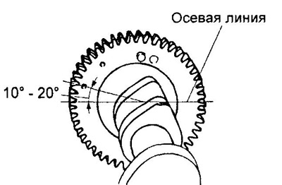
V) Rotate the exhaust camshaft until the mark on the back of the gear makes an angle of 10-20°with the camshaft centerline as shown.
G) Lubricate the journals, cams and gears of the #2 camshaft with engine oil.
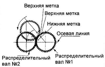
d) Enter the gears of the camshafts, aligning the upper marks, install the camshaft No. 2, rolling it onto the cylinder head.
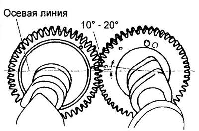
e) After installation, make sure that the marks on the camshafts are located as shown in the figure.
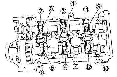
23. Establish covers of loose leaves of bearings of camshafts, tighten bolts of their fastening in several passes in the sequence shown in drawing.
- Tightening torque - 12±2 Nm
24. Remove the auxiliary gear service bolt.
25. Establish a cover No. 1 loose leaves of bearings of camshafts.
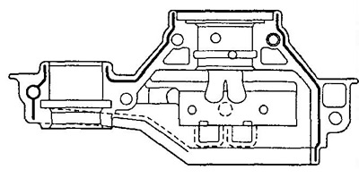
A) Apply sealant to cap #1 as shown.
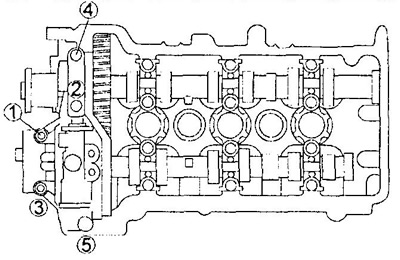
b) Establish a cover No. 1 on a head of the block of cylinders and wrap bolts of its fastening in the sequence shown in drawing.
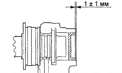
26. Install the plug as shown.
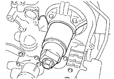
27. Apply some engine oil to the camshaft oil seal and install it into the cylinder head using the special tool.
28. Fix the camshaft pulley with a special tool and tighten the bolt of its fastening.
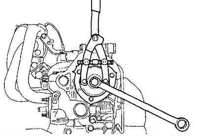
- Tightening torque - 98±10 Nm
29. Check up backlashes in a drive of valves.
30. Install the oil pipe bypass fitting.
- Tightening torque - 52±5 Nm
31. Wrap a bolt of fastening of an oil tube to a head of the block of cylinders.
32. Install the bypass bolt securing the oil tube to the oil filter bracket.
- Tightening torque - 39 + 5 Nm
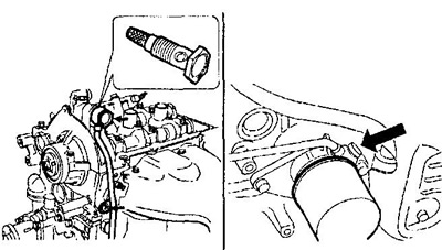
33. Establish a cover of a head of the block of cylinders and wrap bolts of its fastening in the sequence shown in drawing.
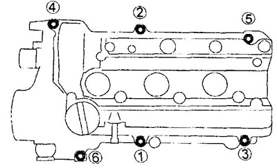
- Tightening torque - 5.5±1 Nm
34. (EJ-VE) Install the DVVT system valve.
35. Install the timing belt.
36. Install the timing belt cover.
37. Install the crankshaft pulley.
- Tightening torque - 98±10 Nm
38. Connect the hose to the cylinder head and intake manifold.
39. Install the ignition coils and cylinder head cover.
- Tightening torque - 6±2 Nm
