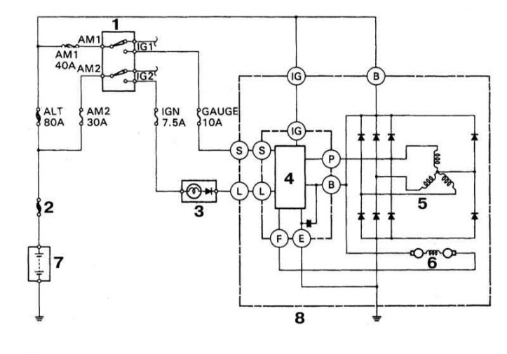
Functional diagram of a typical charge system

1 - Ignition switch; 2 - Main fusible link; 3 - Control lamp charge; 4 - Voltage regulator; 5 - Stator winding; 6 - Rotor winding; 7 - Battery; 8 - Generator
1. Remember that charging system malfunctions are not necessarily related to generator failures. Always do the following simple checks first:
- a. Check the condition and tension of the alternator drive belt (see chapter Vehicle settings and routine maintenance). Replace if necessary;
- b. Check up reliability of a tightening of fixing bolts of the generator;
- c. Check the condition of the wiring and electrical connections of the generator;
- d. If equipped, check the condition of the fusible link installed between the starter traction relay and the generator, or the condition of the large main fuses in the engine compartment. In case of knocked-out elements, identify and eliminate the cause of the overloads that have taken place, then replace the defective components;
- e. Check the condition of all fuses included in the electric circuit of the charging system (refer to illustration above). The location of the fuses and fuses may vary depending on the model and year of manufacture of the car, but the designation remains the same. To be checked: main fuse-link, ALT fuse-link (80A), fusible insert AM1 (40A), fusible insert AM2 (30A), fuse IG2 (7.5A), GAUGE fuse (10A) and fuse ALT (7.5A);
- f. Start the engine and evaluate the intensity of the background noise emitted by the generator;
- g. Check the density of the electrolyte in the battery banks, if necessary, recharge the latter;
- h. Make sure the battery is fully charged - one bad cell can cause the battery to overcharge);
- i. Disconnect the negative and then the positive wires from the battery first. Evaluate the condition of the battery wires at the places where they are connected to the battery terminals of the latter. Check the security of the terminal clamps. After carefully cleaning the contact terminals, connect the battery.
2. Using a voltmeter, measure the voltage supplied by the battery when the engine is off, the measurement result should be approximately 12 V.
3. Start the engine and repeat the test: this time the reading should be 13.5-15.1 V.
4. Turn on the headlights, with a properly functioning charging system, the voltage should first drop, then recover to its previous level.
5. If the value of the measured voltage noticeably exceeds the nominal value, replace the voltage regulator (see Section Check of serviceability of functioning of a starter and a chain of start).
6. If readings are too low, check voltage regulator and alternator (see below).

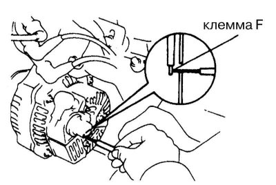
7. Remove the rear cover from the generator. Ground terminal F (refer to accompanying illustration), start the engine and measure the battery voltage. If the measurement result exceeds the allowable value, replace the regulator. If the voltmeter reading is too low, drive the car to a car service workshop to check the output parameters of the generator using an ammeter.

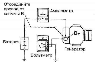
8. If you have an ammeter at hand, checking the output parameters of the generator can be done on your own by a motorist. Connect the ammeter to the system in accordance with the diagram shown in the accompanying illustration.
Note. Instead of an ammeter, you can also use an inductive current indicator, which can always be purchased quite cheaply in car accessories stores.
9. Raise the engine speed to 2000 per minute and read the ammeter reading with the onboard power consumers turned off, then turn on the high beam and turn the heater fan to maximum speed. Compare measurement results with requirements Specifications.
10. At excessively low indications make reconditioning repair, or replacement of the generator.
