Installation height of the foot brake pedal in the released state

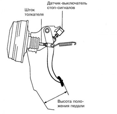
The height of the foot brake pedal is the distance from the floor panel (carpet is not removable) to the center point of the pad rubber pad surface (refer to illustration above). If the measurement result is out of range (see Specifications), an appropriate adjustment must be made.
1. Disconnect the electrical wiring from the brake light switch (see Section Check of serviceability of functioning and replacement of the gauge switch of stoplights).
2. Loosen the locknut (bottom nut) and remove the sensor-switch from its support bracket.
3. Loosen the brake servo pushrod locknut.
4. Rotate the stem to make the appropriate adjustment.
5. Tighten locknut securely.
6. Reinstall the brake light switch and make sure that its plunger freely touches the pedal stop. If necessary, by means of an adjusting nut (top nut) make the appropriate adjustment.
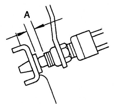
7. Unscrew the sensor-switch one full turn.

8. Measure the distance between the sensor-switch and the pedal stop (refer to accompanying illustration), the value of the protrusion of the plunger), compare the measurement result with the requirements Specifications. If necessary, adjust the position of the sensor-switch on the support bracket accordingly.
9. When you have finished adjusting, securely tighten the sensor-switch jam nut and connect the electrical wiring to the assembly.
10. Make sure that the brake lights are working even when the foot brake pedal is slightly depressed. When you release the pedal, the brake lights should go out.
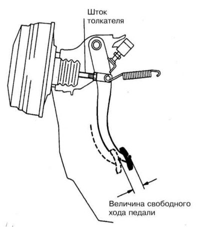
11. Now you need to measure the free play of the pedal.
12. With the engine off, depress the foot brake pedal several times, removing residual vacuum from the vacuum booster assembly.

13. Depress the pedal with your hand until you feel resistance. Measure the distance from the pedal shoe to the floor and subtract the result from the height of the released pedal installation position (refer to accompanying illustration).
14. If the measurement result is out of range (see Specifications), repeat the brake light switch adjustment.

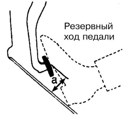
15. Check the amount of back pedal travel: with the engine running (there must be a vacuum in the intake manifold) depress the foot brake pedal to the stop and take the appropriate measurement (refer to accompanying illustration).
16. Compare the measurement result with the requirements Specifications, if necessary, check the condition of the brake system.
17. Check the system for signs of leak development.
