General information
1. Some electrical systems and devices of the car, such as the fuel injection system, horns, starter and fog lights, use a relay to transmit an electrical signal to the element. Each relay has a low current circuit (control circuit), it serves to open and close an electrical circuit with a large current (power circuit). If the relay is faulty, the element will not work correctly. Most of the relays are located in the fuse/engine compartment relay box, some specialty relays are located in a box under the hood not on the right mudguard. On some models, the ABS relays are located under the hood in a separate relay box on the left side of the radiator. If a relay malfunction is suspected, it can be removed and inspected using the procedure below, or contact the dealer's service department or another workshop. Defective relays should be replaced as a unit. The designation of the electrical circuit that the relay controls is often listed on top of the relay, but the label on the inside of the relay box lid should also indicate which circuits they control.
Examination
2. Refer to the appropriate wiring diagram to determine the correct connections for the relay to be tested. However, if you are unable to determine the correct connections from the wiring diagram, you may be able to determine the connections based on the following information.
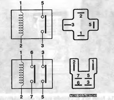
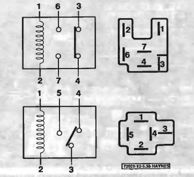
3. Four basic types of relays are used on these vehicles (pic. 5.3, a, b). Some relays are normally open, some are normally closed. Others may be a combination of both types.

Pic. 5.3, a. The two relays shown are normally open relays; the upper relay, when activated, closes one electrical circuit (connects pin 5 to pin 3), the lower relay closes two circuits (pin pairs 6 and 7, 3 and 5)

Pic. 5.3b. These relays are a carousel-closed type, in which current passes through one electrical zinc until the relay is activated; when the relay is activated, this electrical circuit breaks and the second electrical circuit closes
4. In most relays, two of the terminals are related to the electrical control circuit (they are connected to the electromagnet of the relay, which, when energized, closes large contacts to activate the electrical circuit). Other terminals are related to the power circuit (they are connected to each other inside the relay when the coil of the electrical control circuit is activated).
5. Some relays have markings that can help you identify which terminals belong to the electrical control circuit and which belong to the power circuit. If there is no marking, refer to the wiring diagrams at the end of this chapter to determine the correct connection points for checking the turnip.
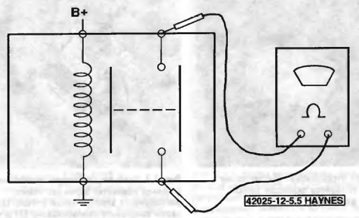
6. To test the relay, connect an ohmmeter to the two power circuit terminals. The device should not show the integrity of the electrical circuit (pic. 5.6). Now install a fused jumper wire between one of the two control circuit terminals and the positive battery terminal. Install another connecting wire between the other control circuit terminal and «weight». When all the wires are installed, the relay should click, and the device should indicate the integrity of the electrical circuit. In some relays, polarity can be critical, so if the relay does not click, try changing the connecting wires at the control circuit terminals.

Pic. 5.6. To test a typical four-pin normally open relay, connect an ohmmeter across the two pins of the salt circuit. The meter should show continuity when the relay is energized and no continuity when the relay is not energized
7. If the relay fails this test, replace it.
