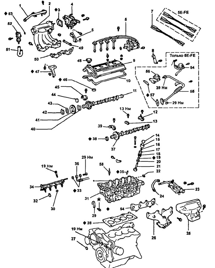
Dismantling of a head of the block of cylinders (5E-FE) 1 - air duct; 2 - intake manifold; 3 - gasket; 4 - throttle body; 5 - bracket for the upper part of the intake manifold; 6 - distributor assembly with high-voltage wires; 7 - vacuum hose; 8 - engine lifting bracket No. 2; 9 - cylinder head cover; 10 - gasket; 11 - intake camshaft; 12 - bearing cover No. 4 of the camshaft; 13 - bearing cover No. 3 of the camshaft; 14 - adjusting washer; 15 - pusher; 16 - crackers; 17 - spring plate; 18 - valve spring; 19 - oil scraper cap; 20 - support washer; 21 - valve; 22 - segment plug; 23 - thermostat housing; 24 - coolant bypass hose; 25 - exhaust manifold heat shield; 26 - exhaust manifold. 27 - cover No. 3 of the timing belt; 28 - cylinder head gasket; 29 - engine lift bracket N91; 30 - insulator; 31 - cylinder head; 32 - spacer sleeve; 33 - gasket; 34 - fuel manifold assembly with injectors; 35 - valve guide sleeve; 36 - fuel supply hose; 37 - exhaust camshaft; 38 - stuffing box; 39 - bearing cover No. 1 of the camshaft; 40 - leaf spring of the camshaft gear; 41 - auxiliary gear camshaft; 42 - retaining ring; 43 - spring washer; 44 - plug of the intake camshaft; 45 - bearing cover No. 2 of the camshaft; 46 - gasket; 47 - intake manifold bracket; 48 - oil filler cap; 49 - hose of the crankcase ventilation system; 50 - gasket; 51 - air bypass valve for exhaust; 52 - air bypass valve for exhaust (ACV); 53 - ring seal; 54 - vacuum modulator of the exhaust gas recirculation system; 55 - pipe of the exhaust gas recirculation system, assembly; 56 - exhaust gas recirculation valve; 57 - gasket.
Installing the cylinder head
1. Install the cylinder head on the cylinder block by installing a new cylinder head gasket on the block
2. Establish bolts of fastening of a head of the block of cylinders.
Note:
- The cylinder head bolts are tightened in the dev stage.
- If any cylinder head bolt is broken or deformed, replace it.
- A) Apply a light coat of engine oil to the threads and under the heads of the mounting bolts.
- b) Install and using an 8 mm wrench progressively tighten in several passes (at least 3) block head bolts in the sequence shown in the figure.
- Tightening torque - 44 Nm
Note: bolts (A), marked in the figure are longer than the bolts (IN).
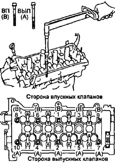
If any bolt is not tightened to the correct torque, replace the bolt.
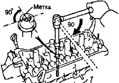
- G) Apply paint marks to the front of the cylinder head bolts.
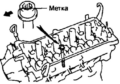
- d) Tighten the cylinder head bolts 90°.
- e) Check that the inked mark is 90°from its original position.
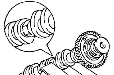
3. Assemble the intake camshaft.
- A) Clamp the hex section of the camshaft in a vise.
Note: Do not damage the camshaft.
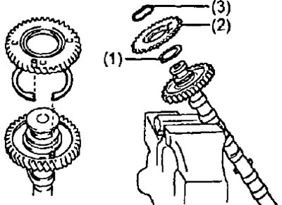
- b) Install the following parts:
- leaf spring (3) camshaft gears;
- auxiliary gear (2) camshaft drive;
- spring washer (1).
Note: Align the pins on the gears with the ends of the leaf spring (3), as it shown on the picture.
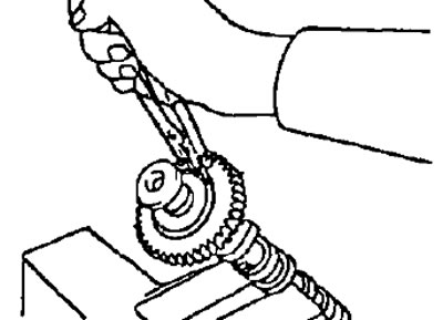
- V) Using pliers, install the retaining ring.
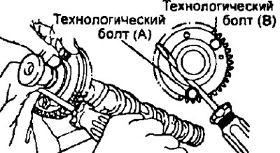
- G) Insert process bolt (A) in the technological hole of the auxiliary gear of the camshaft drive.
- d) Using a screwdriver, align the hole of the camshaft drive main gear and the sub gear by turning the camshaft drive sub gear clockwise; then install the technological bolt (IN).
4. Install the camshafts
Note: when installing camshafts, it must be taken into account that the axial clearance is very small; therefore, the shafts must be laid in the bed of bearings strictly horizontally, without distortions, in order to avoid jamming and / or damage to the shafts.
To avoid this, follow the following sequence of procedures.
- A) Apply a layer of engine oil to the end thrust surfaces of the camshaft.
- b) Install the intake camshaft as shown, with the intake camshaft service bolt up and the #3 and #4 cam lugs down.
- V) Install the four bearing caps in their respective locations.
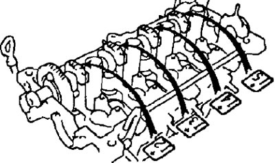
- G) Temporarily tighten the bearing cap bolts by alternately tightening the right and left bolts in the sequence shown in the figure.
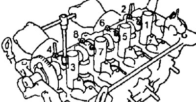
- d) Apply engine oil to the ends of the exhaust camshaft.
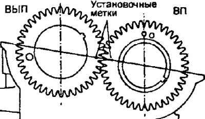
- e) Engage the exhaust and intake camshaft drive gears by aligning the alignment marks on these gears with each other.
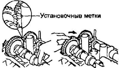
- and) Keeping the gears engaged, roll the exhaust camshaft into its journals on the cylinder head.
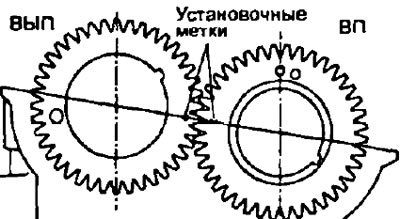
- h) Push lightly on the exhaust camshaft towards the front of the engine, but do not apply much force.
- And) Install the four exhaust camshaft bearing caps.
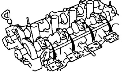
- To) Temporarily tighten the bearing cap bolts evenly and alternately.
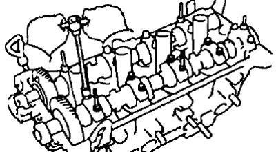
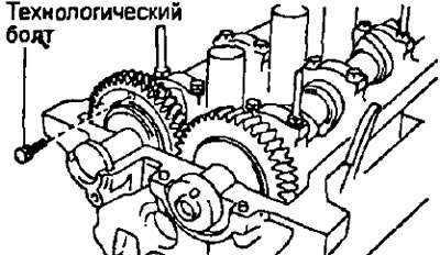
- l) Turn away a technological bolt.
- m) Clean the surface of the N22 bearing cap and apply sealant to the area indicated in the figure.
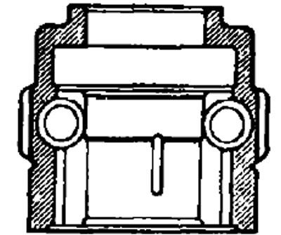
- n) Install the Ne2 bearing cap, and then check that there is no clearance between the cylinder head and the contact surface of the bearing cap.
- O) Tighten the #2 bearing cap bolts evenly and alternately for a while.
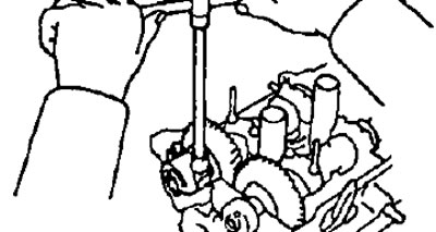
- P) Install the intake camshaft cap.
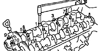
- R) Install and tighten the ten intake camshaft bearing cap bolts alternately and evenly in the sequence shown in the figure.
- Tightening torque - 13 Nm
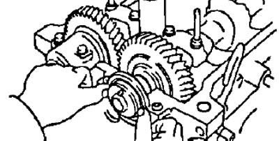
- With) Apply sealant to the new camshaft seal and install the new seal as deep as possible into the cylinder head.
- T) Clean the surface of the #1 bearing cap and apply sealant to the area indicated in the illustration.
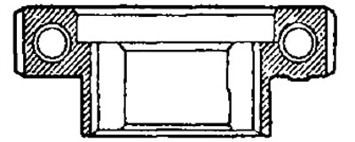
- at) Install bearing cap No. 1, then check for clearance between the cylinder head and the contact surface of the bearing cap
- f) Tighten the #1 bearing cap bolts evenly and alternately for a while
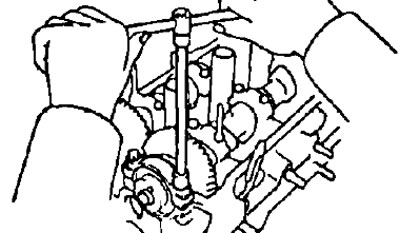
- X) Install and tighten the ten exhaust camshaft bearing cap bolts alternately and evenly in the sequence shown in the figure.
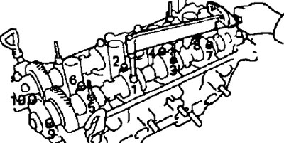
- Tightening torque - 13 Nm
- c) Turn the camshafts and check the alignment of the alignment marks.
5. Install the camshaft sprocket.
- A) Align the exhaust camshaft locating pin with the pin groove on the sprocket and install the sprocket.
- b) Holding the camshaft with a wrench at the hex section. tighten the toothed pulley bolt.
- Tightening torque - 50 Nm
6. Install the intermediate pulley and tighten the bolt.
- Tightening torque - 27 Nm
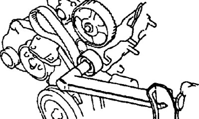
7. Install the timing belt.
- A) Rotate the crankshaft pulley and align the notch on the pulley with the alignment mark (ledge) on cover #1 of the timing belt.
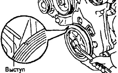
Note: Check that the timing belt is correctly installed on the crankshaft sprocket and on the oil pump pulley.
- b) Rotate the camshaft and align the alignment hole on the camshaft sprocket with the alignment mark on the Nel bearing cap.
- V) Place the timing belt on the camshaft sprocket as shown in the illustration and turn the camshaft to install the belt.
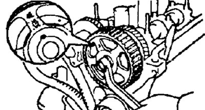
- G) Loosen the idler pulley mounting bolt until it moves slightly under the action of the spring.
- d) Rotate the crankshaft pulley two turns (from TDC to TDC).
Note: Turn the crankshaft only clockwise.
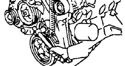
- e) Check that all alignment marks on all pulleys are aligned.
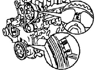
If the alignment marks are not aligned, then remove the timing belt and reinstall it.
8. Install timing belt cover #3.
9. Install the alternator drive belt. Temporarily tighten the axle bolt nut and adjust the belt tension.
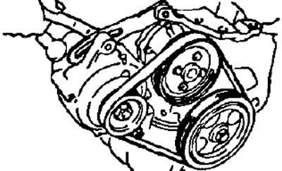
10. Install timing belt cover #2 by installing gasket and tighten with four bolts.
11. Install the cylinder head cover
- A) Apply sealant to the cylinder head as shown.
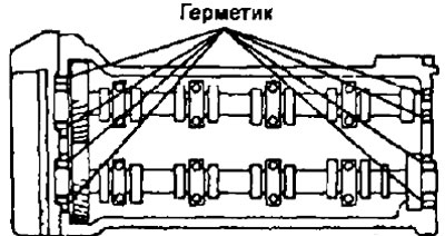
- b) Install the gasket on the cylinder head cover.
- V) Install the cylinder head cover and tighten the five sealing washers.
- Tightening torque - 7 Nm
12. Install the intake manifold.
- A) Install new gasket and intake manifold, tighten three nuts and three bolts
- Tightening torque - 19 Nm
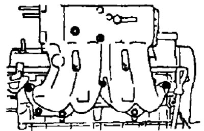
- 6) Install the manifold bracket by tightening the two bolts and nuts.
- Tightening torque - 19 Nm
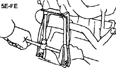
13. Install the air tube by tightening the two bolts.
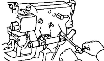
14. Install the injectors and fuel manifold.
15. Install the throttle body.
16. Install the air bypass valve to the outlet.
- A) Install the O-ring from the air bypass valve.
- b) Apply soapy water to the O-ring.
- V) Connect two bolts, wire "grounding" and an air bypass valve to the outlet.
- G) Connect the valve connector.
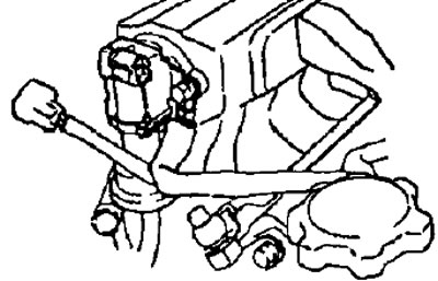
17. Install the exhaust manifold.
- A) Install a new gasket and tighten the six nuts.
- Tightening torque - 47 Nm
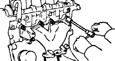
- b) Install the heat shield and tighten the three bolts.
- Tightening torque - 8 Nm
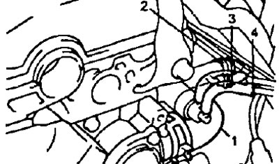
18. Install thermostat and outlet tubes
- A) Remove the old sealing material and clean the surface as shown in the figure.
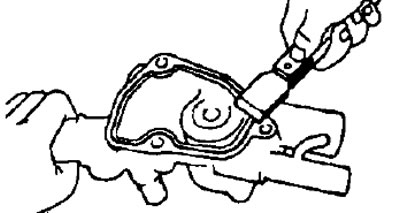
Note: Use a scraper or scraper to remove and clean surfaces with a non-residue solvent.
- b) Apply sealant as shown.
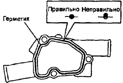
- e) Install the thermostat and tighten the two bolts.
- Tightening torque - 19 Nm
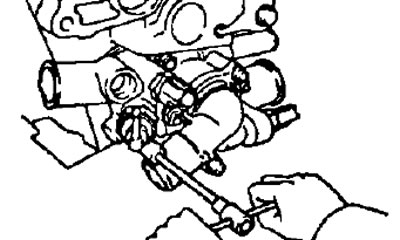
- G) Connect the following hoses:
- Coolant Inlet Hose (1).
- Heater outlet hose (2).
- coolant bypass hose (3)
- Two vacuum hoses of a thermally controlled pneumatic valve (4).
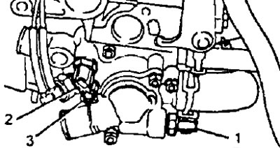
- d) Connect the following connectors:
- Sensor connector - switch for coolant temperature (to the electric fan drive of the cooling system) (1).
- Connector coolant temperature sensor (2).
- Coolant temperature gauge sensor connector (3).
- (Models with automatic transmission) Coolant Temperature Switch Sensor Connector (4).
18. Install the EGR pipe, vacuum modulator and EGR valve.
- A) Install the gasket and EGR valve, tighten the two nuts.
- Tightening torque - 17 Nm
- b) Install the vacuum modulator.
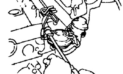
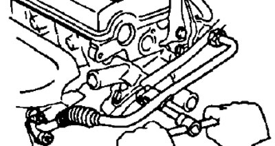
- V) Install a new gasket and EGR pipe by tightening the two fastening nuts. Tighten the union nut of the tube.
- Torque:
- union nut - 39 Nm
- fastening nuts - 29 Nm
19. Connect the vacuum hoses, power steering pump.
- A) (Models with automatic transmission) Connect the following hoses:
- Vacuum hose from throttle actuator (1).
- Vacuum hose from EGR valve (2).
- Three vacuum hoses from the EGR vacuum modulator (3).
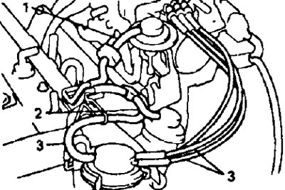
- b) Connect the vacuum hose from the fuel vapor accumulator.
20. Install spark plugs.
- Tightening torque - 19 Nm
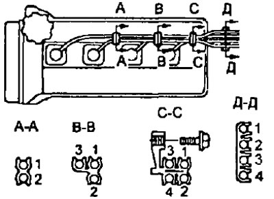
21. Connect the high voltage wires by tightening the bolt securing the high voltage wire holders to the cylinder head cover.
