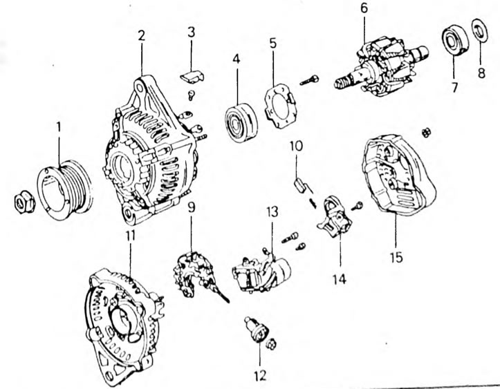
Pic. 265. Installation drawing of an alternating current generator. 1. Pulley; 2. Drive bearing shield; 3. Rubber insulation; 4. Front bearing; 5. Bearing plate; 6. Rotor; 7. Rear bearing; 8. Bearing washer; 9. Rectifier diodes; 10. Brush; 11. Rectifier cover; 12. Terminal insulation; 13. Regulator; 14. Brush holder with cover; 15. Back cover
- Unscrew the armature shaft nut and remove the pulley. When unscrewing the nut, keep the pulley from turning with the old V-belt. A two-arm puller may be required to remove the pulley.
- Remove the key from the shaft.
- Unscrew the brush holder and regulator from the back of the generator.
- Unscrew the nuts or bolts of the rear cover and remove the cover.
- Unscrew the four nuts and separate the stator from the front cover. To do this, you can lightly tap the front bearing cover with a plastic hammer or use a two-jaw puller.
- Place the bearing shield and rotor under a press and press the rotor out of the bearing. If you need to remove the bearing from the shield, press out the bearing after unscrewing the bolts and removing the bearing retaining plate.
- Remove the rear rotor bearing from the rotor shaft using a suitable puller.
- Unscrew the fastening of the diode board, terminals and insulation and remove the stator from the diode board from the commutator bearing shield.
