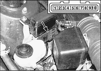
1. Disconnect from the electronic unit located under the brake master cylinder (V6 engine), connector and perform the following checks referring to the diagram (see subsection 12.2.2.)
2. Check for battery voltage at terminal 9 of the connector.
3. Check for 5V on pin 4 of the connector. If there is no voltage, then hand over the processor unit for repair.
4. Check for a fluctuating 0.1-4.5V voltage on pins 5, 6, and 7 of the connector (to do this, ask the assistant to turn on the starter). If there is no voltage, then hand over the processor unit for repair.
5. Check the connection to terminal 3 ground.
6. If the tests give a positive result, then disconnect the connectors on each coil and check for a signal using the LED (see subsection 3.4.5.). If there is a signal, then check the integrity of the circuit from the ignition unit to the coil. If the circuit is OK, then replace the ignition unit.
