- Rated voltage - 10-14 V
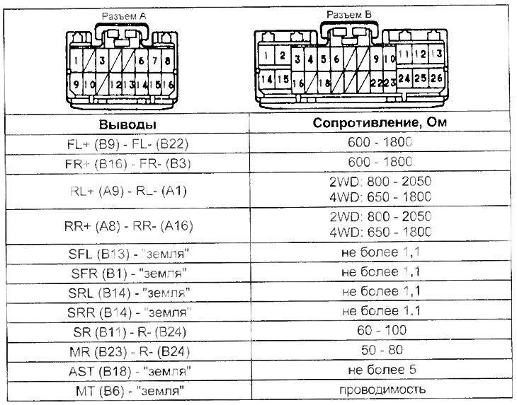
2. With the ignition off, disconnect the ABS control unit connector and check the resistance and continuity between the ABS control unit connector terminals (see table "Resistance between conclusions of a socket of the electronic block of management ABS").
3. Measure the voltage at the terminals of the ABS control unit connector with the ignition on (see table "Voltage at the terminals of the ABS control unit connector").
Note: Please check battery voltage before measuring (with the ignition on - 10 -14 V) and resistance between terminal "Earth" connector and body (with the ignition off - no more than 5 ohms).
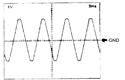
4. Using an oscilloscope, at a vehicle speed of 30 km / h, check the signal between the terminals of the A3S control unit connector: "FL+" - "GND", "RL+" - "GND", "FR+" - "GND", "RR+" - "GND". Value of division (cells) 1 V and 2 ms.
Note: As the speed increases, the pulse width should decrease. and the tension increases.
5. Using an oscilloscope, at a vehicle speed of 30 km / h, check the signal between the indicated terminals of the ABS control unit connector:
- (For models before 1996) "FLO" - "GND", "RLO" - "GND", "FRO" - "GND", "RRO" - "GND".
- (For models from 1996) "FLO" - "GND", "SPT" - "GND".
Value of division (cells) 5 V and 2 ms.
Note: As the speed increases, the pulse width should decrease.
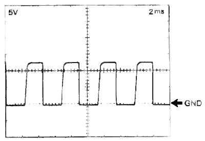
Table. Resistance between the terminals of the ABS control unit connector.
Models up to 1996
Models since 1996
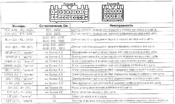
Table Voltage at the terminals of the connector of the ABS control unit. Models up to 1996
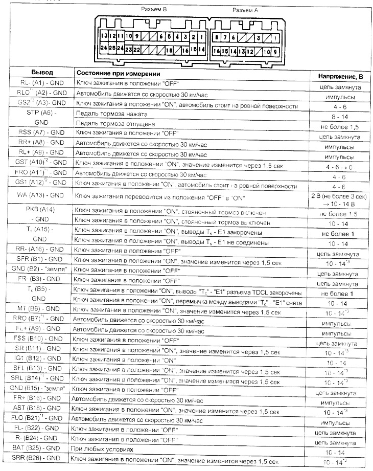
*1: models with TRC, 4WS (output only "FLO").
*2: 4WD models.
*3: If the ABS indicator is on, the ABS system is malfunctioning (because the ABS indicator is on, the voltage, for the specified time, drops from 10 - 14 to 0 V).
Table. Voltage at the terminals of the ABS control unit connector (continuation). Models since 1996
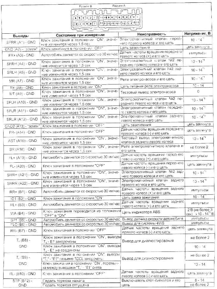
*1: If the ABS indicator is on, the ABS system is malfunctioning (because the ABS indicator is on, the voltage, for the specified time, drops from 10 - 14 to 0 V).
