Removing
Note: remove the modulator as shown in the picture "pressure modulator". Install in the reverse order of removal. After installation, bleed the brake system and check for leaks.
Checking the parking brake sensor
1. Check the continuity between the output "1" And "earth" sensor connector.
- Lever arm (pedal) parking brake applied (pressed) - circuit is closed
- released (released) - open circuit
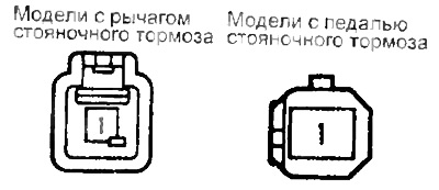
If the circuit condition is not as specified, then the parking brake switch is faulty.
Checking the brake light switch
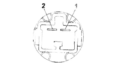
1. Check continuity between terminals "1" And "2" brake light switch connector. When the pedal is pressed, the conductivity should be, when the pedal is released, there should not be any conductivity. Otherwise, replace the brake light switch.
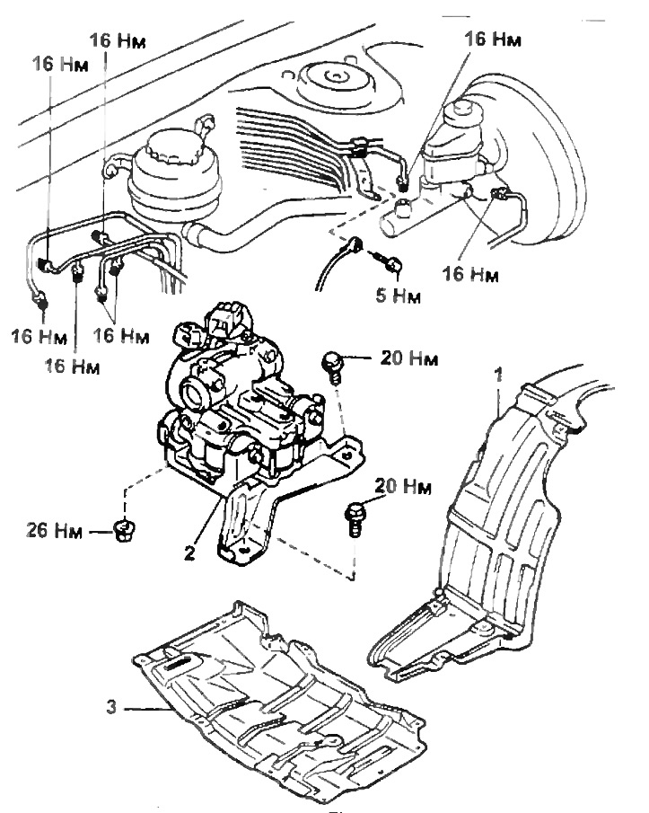
pressure modulator.
1 - fender liner,
2 - pressure modulator,
3 - engine protection cover.
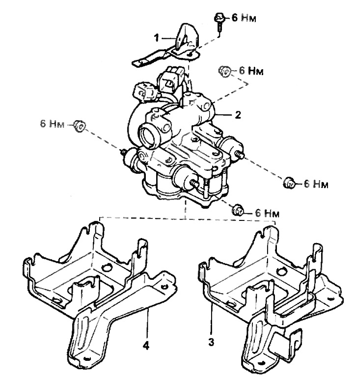
pressure modulator (continuation).
1 - bracket,
2 - pressure modulator,
3 - pressure modulator bracket (petrol engine models),
4 - pressure modulator bracket (diesel engine models).
Checking the pressure modulator
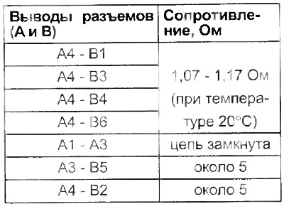
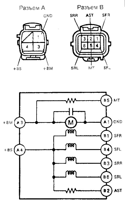
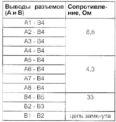
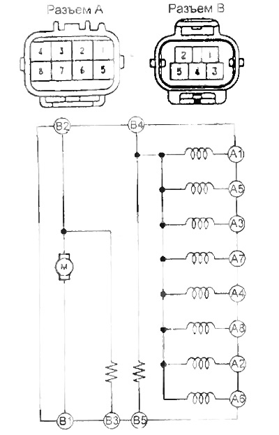
1. Check continuity and resistance between pressure modulator connector pins as shown in the table.
If the resistance between the indicated terminals does not correspond to the values given in the table, then the pressure modulator is faulty.
Models up to 1996
 |  |
Models since 1996
 |  |
